
because woodworking, along with video and computers, is one of my primary hobbies, i decided that i would put together something. what exactly this would contain, i wasn't sure. no, i don't want to "sell" or promote any products. what to do?
well, as happens in life, a recent faux pas led me to decide what the initial content should be on this page. yes, i leapt before thinking, while building a mantle for the fireplace. my wife wanted a nice mantle and i told her that it would be easy--and quick. compared to my other projects, this would be a breeze!
i decided that i would make a simple shelf, having crown moulding as a base to give it apparent thickness, and having solid oak reinforcement underneath. of course, esthetics demanded that the moulding cant inward 45 degrees. a quick sketch gave me an adequate "bill of materials" and i ran out to the local builder's square (r.i.p.) for the supplies.
"since i'm mitering these together with 90degree corners and a 45degree cant," i thought, "i have to set the miter saw at a 45 degree miter, 45 degree bevel." i measured the mouldings and made the cuts. without forethought, hesitation, or my woodworking guardian angel whispering "you idiot!" in my ear, i set the compound miter saw to 45degrees miter, and 45degrees bevel. i took the front piece, cut it and then glued and brad-nailed it to the shelf. (broke another golden rule of woodworking: dry fit first!) looks good so-far. now for the side pieces. (ok, all of you that know, stop laughing!)
"hmm, what's wrong with this picture? didn't i set it to 45/45? why do they want to mate at such an ugly angle?" i ran inside, grabbed a piece of paper and solved the problem....had i just taken the few minutes beforehand! but, you can now benefit from my mistake; however, instead of just giving the answer and the formulae, and because it's inherently good to teach and to learn, here is my humble attempt to walk you through the general problem: to help you visualize what's going on. (yes, graphics are necessary here.)
first, some definitions and concepts.
sin(q) = opposite / hypotenuse
cos(q) = adjacent / hypotenuse
tan(q) = opposite / adjacent = sin(q) / cos(q)
cotangent(q) = cotan (q) = 1 / tan(q)
arctangent(tan(q)) = q
so, what are these projections?
well, imagine that you're standing in front of a telephone pole that has fallen down (actually, it's magically levitating at eye level so we only have to deal with one projection, not two). now, the pole is 35 feet long and is pointed away from you at 23 degrees. how long does it look to you? simple, imagine the overhead view of you and the pole (figure 1). without specifically getting into how you see objects (i.e., reflected rays of light), assume that you see the pole because the suns rays--like that of a movie projector--come from straight behind it and project its image on a sheet of glass that's perpendicular to your view. this projected image is the "adjacent side" of a right triangle. (also, we have to assume that your distance from the projected image is sufficiently close so that you see the projections full length.) therefore, the pole's apparent length is:
cos(23 degrees) = projection / telephone pole length
projection = cos(23 degrees) * 35 feet
projection = 32.2 feet
figure 1
that was easy and painless.
now that you have an idea of the meaning of "projection" and have been reminded of the basic equations for right triangles, we're ready to tackle the compound miter problem. but, we need to define the known and unknown values of the problem. they are (referring to figure 2 below):
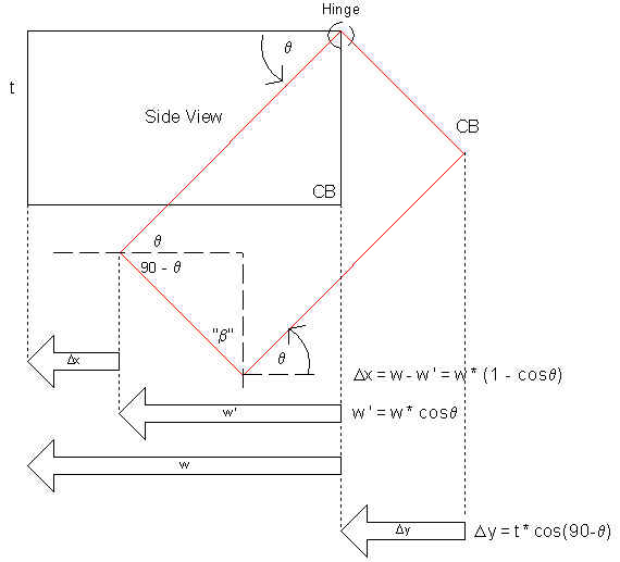
figure 2
notice that i've put many of the projection "vectors" (these are the arrows), as seen from the side of the inclined piece, in the upper diagram for the work piece in its initial and final (i.e., rotated by q) positions. also, i have transposed the vectors to the top view in the lower figure of the figure 2 pair.
miter angle of the moulding
let's tackle the miter angle first, shall we? there are a few of ways we can go about solving this problem. first i'll use a bit of a short-cut (just to help you visualize the problem at hand and to demonstrate how to apply some a priori knowledge). then i'll present one "full" solution. (i'll forgo using spherical coordinates.) as the astute observer can see, figure 2 uses a 90 degree corner to illustrate what will be the general solutions for both the miter and bevel.
you know that for 90 degree corners the miter is 45 degrees if the angle of inclination ("tilt", q) is 0 degrees. now imagine piano hinges affixed to the top edge of each work piece (figure 2), and that the hinges rotate in unison. now, incline the workpieces to q as shown in the side view, which indicates the initial position (blue rectangle) and final position (red rectangle) of one piece. looking from above, we would perceive the width (i.e., "projection", w') of each piece as being narrower. we would also see that the inside edges of the joint open up: the butt joint separates. using the concept of projections, we can easily find w ' = w cos(q). (the side view shows a bunch of projections.)
"so what, we know the perceived width!", you mutter. well, look at the top view. when the pieces rotate to q degrees we see that the inner edge of each piece moves away from it's original position by Dx. well, after each piece's inner edge moves by Dx, we want the inner corners to meet at a given point (green dot in top view at the end of the "corner motion" arrow).
so we have to miter the piece such that, as it is tilted by q, the inner corners are touching. again, referring to the top view, we see that we want the corner piece "A" to move from its original position (magenta dot) to the green dot. therefore, the miter angle required is:
tan(a) = w' / w
a = atan[ w *cos(q) / w]
therefore, a is
a = atan[cos(q)]
now, we're going to make use of an orthogonal view (figure 3) of moulding "A" tilted at q degrees. since we're only interested in the miter joint, we need not concern ourselves with the length of the moulding and can, therefore, draw a simple triangle tilted at q. it should be noted that to be consistent with figure 2, i have defined the desired miter angle as (90 - a).
figure 3
note that the triangle has a base = w (i.e., the width of the moulding). we want this triangle to look like (i.e., project) a triangle having an angle of g below the vertex having angle a, and we know that w ' = w *cos(q). because the edge that is hinged will not change in apparent length, L = L, and L can be found readily since we want an angle g and can easily find w' from q:
L = w' * tan(g)
having found L, the angle (90 - a) can be readily found:
(90 - a) = atan [ w ' / L ]
90 - a = atan [(w * cos(q)) / (w * tan(g )) ]
a = 90 - atan [(w * cos(q)) / (w * tan(g) ) ]
therefore,
a = 90 - atan[cos(q) / tan(g)]
it's all in the bevel
great, we've found the miter angle. unfortunately, as you tilt the pieces to q and keep the top edges of the joint together, the bottom edges separate along the joint. so what's the bevel angle required to keep those together?
let's first sketch what has happened. since a was derived as a function of g and q, these are implicit in the following sketch. what i mean by "implicit" in this context is that the drawing is not technically correct. you'll see why.
figure 4
referring to figure 4, the bevel cut angle (b, angle required to get a vertical joint) is very easily found from the following observations:
Dy ' = Dy * sin(90 - a)
the bevel angle, b, is found from
b = atan[Dy ' / { t*sin(90 - q) }]
b = atan[ {t*cos(90 - q) * sin(90 - a) } / {t*sin(90 - q)} ]
therefore, b is
b = atan[ cot(90 - q) * sin(90 - a)]
well, just so you can have a cheat-sheet at your disposal for a few values for your typical picture frame and crown moulding applications, having 90 degree corners, i'm including this small table. print it and keep it handy. remember, houses rarely have exactly 90 degree corners. if you're anal retentive, you could measure the angle of each corner and substitute into the equations accordingly. or you could just assume 90 degrees, make the cuts, and cope the joints. (although, you'll do that most likely, unless you can set your saw within the required tolerances.)
| Corner angle = | 90 | degrees | ||||
| Tilt from horizontal | miter box angle via "observation method" | wood's miter angle relative to "hinged" surface | "exact" derivation result for wood's miter angle | Bevel | ||
| q [degrees] | q [rad] | a [deg] | miter [deg] | a [deg] | b [deg] | |
| 0 | 0 | 45 | 45 | 45.0 | 0.0 | |
| 5 | 0.09 | 44.9 | 45.1 | 45.1 | 3.5 | |
| 10 | 0.17 | 44.6 | 45.4 | 45.4 | 7.1 | |
| 15 | 0.26 | 44.0 | 46.0 | 46.0 | 10.5 | |
| 20 | 0.35 | 43.2 | 46.8 | 46.8 | 14.0 | |
| 25 | 0.44 | 42.2 | 47.8 | 47.8 | 17.4 | |
| 30 | 0.52 | 40.9 | 49.1 | 49.1 | 20.7 | |
| 35 | 0.61 | 39.3 | 50.7 | 50.7 | 23.9 | |
| 40 | 0.70 | 37.5 | 52.5 | 52.5 | 27.0 | |
| 45 | 0.79 | 35.3 | 54.7 | 54.7 | 30.0 | |
| 50 | 0.87 | 32.7 | 57.3 | 57.3 | 32.8 | |
| 55 | 0.96 | 29.8 | 60.2 | 60.2 | 35.4 | |
| 60 | 1.05 | 26.6 | 63.4 | 63.4 | 37.8 | |
| 65 | 1.13 | 22.9 | 67.1 | 67.1 | 39.9 | |
| 70 | 1.22 | 18.9 | 71.1 | 71.1 | 41.6 | |
| 75 | 1.31 | 14.5 | 75.5 | 75.5 | 43.1 | |
| 80 | 1.40 | 9.9 | 80.1 | 80.1 | 44.1 | |
| 85 | 1.48 | 5.0 | 85.0 | 85.0 | 44.8 | |
| 90 | 1.57 | 0.0 | 90 | 90.0 | 45.0 |

recently i was e-mailed inquiring about the miter angle required to join a crown moulding running up a stairwell and intersecting with a crown moulding installed flush against a hallway wall. altough i have not yet formally solved the problem, some quick sketches lead me to one possible solution.
look to this section for more formal details about how to attack this problem. for now, i will include only the (modified) e-mail which i sent the inquirer. this is one possible solution.
first, the moulding which runs down the stairwell at 30degrees, will have to be pitched away from the wall at 30degrees also. this is simply because the 30degree pitch along the length causes an apparent height change upon its intersection with the hallway wall (i.e., the projection). now, the corner: what to do? well i started on the math, but then i noticed something with the corner in my perspective drawing: i assumed that the hallway moulding would also have a compound miter. but it can't, if you want the profiles are to match up! a compound miter, for the stairwell moulding to join with the hallway moulding and maintain a profile match, would require that the stairwell moulding to "pass into" the ceiling. but this is impossible (physically). so, the solution is a butt joint.
miter the stairwell piece at 30degrees (no bevel). also, plane off the top of the moulding at 30degrees so that it rests flush against the ceiling. (you may also choose to plane off the back of the moulding at 60degrees so that the moulding lays flush against the wall, but this is not necessary.) temporarily tack it to the wall at a 30degree cant. and tack the hallway piece to the wall (allowing it to overlap the hallway moulding). trace out the butt joint of the stairwell piece on the back of the hallway piece. remove the hallway piece and cut out the excess. that's my solution.
oh, if you don't joint the back of the stairway piece at 60 degrees, then when the hallway moulding is tilted by 30degrees, there will be a small void between the wall and the bottom edge of the stairwell moulding which will have to be filled.
well, there you have it. a bit of a trig lesson and the equations required for the miter and bevel angles for crown mouldings, picture frames, or anything that your heart desires to join with compound angles. don't make the same mistake i made! think before you leap.
someday (soon?) i hope to develop an on-line calculator. perhaps even add a small 3d graphical representation of compound miter angles and the resulting "frame."
hope you enjoyed it, now either go back to my homepage or go fire up that compound miter saw!
"What's that?"
"It's a conduit bender."
"What's it for?"
"To bend conduit."
"Urghhhhh!", so now I've got a conduit bender hanging on the wall.
--Tim Allen
questions, comments, concerns? e-mail me.
This site developed and maintained by greg kimnach.

this page created and last modified in spring 1999